In our last article on geometric dimensioning and tolerance, we discussed the basics of GD&T and the many benefits of using it for CNC design. Today, we continue by looking at the other half of GD&T. This concludes the introduction to GD&T, covering tolerancing guidelines and tolerancing symbols.
GD&T Tolerancing Symbols
There are different tolerancing symbols used to communicate GD&T information amongst product designers and engineers. Because GD&T can be considered based on different features, we can categorize our tolerancing symbols into 5 groups. Let’s take a closer look at each of these:
• Location controls
GD&T symbols related to location are used to define the true positon of features using liner measurements. This is achieved with a datum, which indicates the location tolerance in relation to position, concentricity and symmetry.
o Position defines the location of the feature relative to other features or to a datum. It is the most complex and most versatile location control tolerance. Position is used to define coaxiality of features and the distance between features, and specifies how much a feature can deviate from its true position.
o Concentricity defines the accuracy of concentricity of the axes of two cylinders (deviation from the center). It specifies the location of a feature’s axis to the axis of the datum.
o Symmetry is used to ensure that non-cylindrical parts have similar geometry across the datum plane. It specifies the accuracy in the symmetricity of a feature in relation to the datum.
• Form controls
Form controls define the geometry and shape of features. It defines the level of flatness, circularity, straightness and cylindricity.
o Flatness measures the degree or level of straightness of a surface in multiple dimensions. It describes the feature irrespective of any other datum or features. Flatness tolerance references two parallel planes that define where the entire reference surface should lie. It is measured between the highest and lowest points on the part surface.
o Circularity describes how close an object is to a true circle. It is the level of roundness of a feature, and its tolerance helps to prevent the form of a circle from being too square, oblong, spherical or not circular enough.

o Straightness
Straightness may be axial or element/surface straightness. It refers to the tolerance responsible for the level of straightness of a line or target feature. It controls how much the lines in a feature can deviate from a straight line.
Straightness tolerance applies to lines and not planes, restricting the line elements from distorting.
o Cylindricity
Cylindricity tolerance specifies how circular and straight a target cylinder or cylindrical feature can be. It controls the value of deviation in a cylinder, and specifies how straight a target and how close a target or feature should be to a perfect circle
• Profile controls
Profile tolerance indicates the 3D boundary area or tolerance zone around the surface wherein the elements of the surface must lie. See more on line and surface profile below:
o Line profile is used to evaluate a 2-dimensional cross section area relative to an ideal shape. Here, the tolerance or boundary area is marked by two offset curves unless specified otherwise. Line profile tolerance will therefore indicate any deviation in the profile line that falls outside the tolerance zone.
o Surface profile
Surface profile requirements indicate whether a curvature or surface of a designed part is made to the specifications. Unlike the line profile tolerance that evaluates the deviation of a profile line, the surface profile tolerance evaluates for the entire specified surface.

• Orientation controls are involved with the variations of dimensions at different angles. It is related to datum, and controls the extent of “slant” of a feature, and works with concepts like angularity, parallelism and perpendicularity to refine location controls.
o Angularity is a tolerance zone determine through two reference planes within which the surface, axis or axis of a feature must fall. It controls the surface, axis or center plane of a feature relative to a specified angle that is not 90 degrees, and controls how much a surface, axis or plane can deviate from the angle specified in the design.
o Perpendicularity indicates the accuracy of how perpendicular a feature or surface is to a datum. It specifies and controls the two perfect planes within which the feature plane must lie, and how much a surface, axis or plane can deviate from a 90-degree angle
o Parallelism is quite similar to straightness. The difference is that parallelism is relative to a datum. It specifies two features that must remain parallel to one another. In surface form, parallelism specifies two parallel planes that serve as a tolerance zone.
• Runout controls
Runout controls define the extent to which a feature can differ from specifications with respect to the datum. It is controlled with two tolerance zones – circular and total runout. Runout can exist on any feature that is rotatable around an axis.
o Circular runout is applicable when there is a need to factor the multiple errors that may apply to the feature or surface. It is gauged by rotating the part on a spindle to ascertain the extent of variation or wobble of the part around the rotational axis.
o Total runout encompasses the runout of both the circular feature along with runouts on multiple points of a surface. Total runout accounts for profile, angularity, straightness and other disparities.

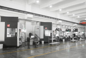
FirstPart CNC Machining in China
FirstPart is one of China’s leading manufacturing hub for Additive, CNC and Conventional manufacturing techniques. We boast of excellent in-house capacity, labor force and logistics while delivering exceptional value for money.
Our array of services includes CNC machining, CNC turning, CNC milling, 3D printing, Rapid Tooling, Die casting, Rapid prototyping, Plastic Injection Molding, Urethane Casting, Aluminum Extrusion, Post-machining/Finishing services and much more.
We offer product tooling, mass production, bridge tooling and low-volume prototyping/manufacturing with very flexible minimum order quantities (1 to 100,000). Our services are online, scalable and innovative, with a team of engineers and design experts available to support you through your entire product development cycle.